Radiasun is the leading manufacturer of cable and satellite meters in the world. Radiasun delivers the most satisfying products and services to the customers all over the world, with our own brands name, and also provides OEM and ODM for the most famous brands in the field.

RA3211 PON Optical power meter
RA3211 - 1310 upstream measurement;
RA3211 - 1490 downstream measurement;
RA3211 - 1550 downstream measurement;
Operation procedures-RA3211 PON Optical power meter
1. Power on-PON Optical power meter
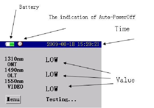
Press POWER ON/OFF to power on the device, the following screen will appear:

There are the measurement results of three wavelength appearing on the screen, i.e.: 1310nm upstream test and 1490nm/1550nm downstream test. The measurement value will appear when there is light passing through the optical channel, otherwise “LOW” will appear.
2.Power Off-PON Optical power meter
While the power meter is on, press and POWER ON/OFF hold it for about 2 seconds to power off the device.
3.Set threshold value-PON Optical power meter
The setting of threshold value will influence the status of the three indicators and the status of measurement results. For example, if the option “1310nm” is set as: -15, -30, -40, it means that: when the optical power measurement value of 1310nm is greater than -15dbm, the optical circuit will be normal, the moment the 1310nm indicator turns in green; when the optical power measurement value of 1310nm is within -15dBm~-30dBm, it means that problems may exist in optical channel but it is still usable, the moment the 1310nm indicator turns in yellow; when the optical power measurement value of 1310nm is within -30dBm~-40dBm, it means that there exists abnormal in optical channel, the moment the 1310nm indicator turns in red; if the optical power measurement value s less than -40dBm, the moment the 1310nm indicator turns in dark, “LOW” appears in the LCD area where the results are displayed. To conclude, “green” represents “Pass”, “yellow” represents “warning”, “red” and “dark” represent "Error". So does 1490nm or 1550nm test.

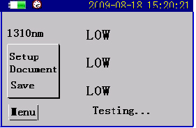
(1) While in main interface, press MENU, a menu as below will pop up:
(2) Select the setting you desire by pressing UP and DOWN, press Enter, to enter the setting interface as shown below:
(3) Here user can set language, time, auto power off, incidental mode, threshold value, calibration. For example, if you select “threshold value”, the setting interface will appear as below.
(4) Press MENU to select option. Press UP or DOWN to increase or decrease the threshold by 1 respectively. If the option is Save, press ENTER , the change will take effect.
(5) If the operation is Default, press ENTER, the threshold value will be rest to be default value.
4.Calibration-PON Optical power meter<
This ability is designed to set tolerance, it will increase the power reading by 1.
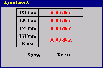
(1) Enter setting interface, select Calibration, press , the calibration screen will appear as below:
(2) Press to select the option you desire. Press or to increase or decrease the calibration value by 0.01 respectively. If the option is Save, press , the change will take effect.
(3) If the operation is Default, press , the threshold value will be rest to be default value.

5. Data upload-PON Optical power meter
The measurement results can be saved in the device, or be uploaded to PC using upper computer software. Connect one end of data cable to the port of PC Link in the device, the other end USB port of PC, run the upper computer software, and set the software as per default configuration, then you can directly click “Upload” on upper computer to transfer the data to PC.
6. Measurement procedures-PON Optical power meter
(1) Press to power on the meter, enter threshold value setting interface to set threshold value.
(2) Connect in the optical fibre to be tested.
It supports measurement of three wavelength i.e.: 1310nm upstream, 1490nm and 1550nm downstream at the same time.
For example: threshold value is (+3dBm, -10dBm, -30dBm), the measurement readings of the meter are: the value for 1310nm upstream test is +1dBm, which is within +3~-10dBm, it means that the optical circuit is normal, so in the testing screen, the power value for 1310nm is displayed in green; if the power value falls within -10dBm~-30dBm, it means that the optical circuit may be wrong but is still usable, so in the testing screen, the power value for 1310nm is displayed in yellow; if the power value falls outside of threshold value, it means that there exists abnormal in optical circuit, the power value of the optical circuit is too strong or too weak, so in the testing screen, the power value for 1310nm is displayed in red. So does 1490nm and 1550nm test.

